 |
|
|
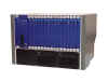
Accord MGC-100 Table of Contents Introduction In recent years, developments in the computer industry have made it increasingly easy for companies both large and small to do business in a more cost-effective manner. Developments which have included the Local Area Network (LAN), Wide Area Network (WAN) and, of course, the ubiquitous Internet have made it easier for us to communicate in the �global village� that represents today�s world-wide business community. Invariably, the most effective developments have involved messaging in one form or another, whether that be electronic mail (e-mail), Electronic, Document Exchange (EDI) or workflow. Few can deny the tremendous impact such messaging applications have had on the way companies work today. The only limitation, of course, is that - although much quicker than writing a letter - computerised messaging systems still do not work in real time. Often there is a requirement for real-time interaction, when only a telephone conversation or face-to-face meeting will do. The face to face approach is frequently preferable to telephonic communication, particularly when it is necessary to accurately gauge a person�s reaction to a situation - it is too easy to hide feelings when you don�t have to look someone in the eye. Likewise, personal meetings are essential when discussing a physical item which cannot be scanned or faxed, or when two people need to work simultaneously on a single document or presentation. Yet it is all too often impossible to get key people together when they may be located hundreds or thousands of miles apart. Rich media communication can provide a solution to this problem, offering real-time sharing of data, audio and video between two or more conferencing end-stations simultaneously. Creating a virtual meeting on a PC or TV screen is proving an increasingly attractive way for many companies to save time and money. Meetings can now be scheduled almost at a moment�s notice, involving people situated in different offices, and even on different continents. Low-cost, high-power PC�s and communications links have allowed a number of videoconferencing vendors to produce desktop systems to complement - or even sometimes replace - the bulky and expensive room-based systems used until now. This has allowed many organisations to put PC-based videoconferencing facilities into small branch offices or even into the homes of key executives to extend the reach of the virtual meeting even wider. However, in order to make rich media communication truly ubiquitous, there are two significant problems to be overcome. The first is that you need to be able to conference between more than two people simultaneously, and the second is that equipment from different vendors needs to interoperate effectively. Like the telephone, today�s videoconferencing systems are essentially point-to-point communication mechanisms, whereas the real requirement is often for a whole group of people to conduct their virtual meeting together. The only way to do this is to have each of the conferencing end-stations participating in the same conference via a �hub�. In the conferencing world, this hub is known as the Multipoint Control Unit (MCU), which can automatically assemble multiple video streams into a single multipoint meeting. Advanced models are capable of organizing dozens of users into multiple simultaneous conferences. Most long-distance carriers now provide transparent dial-up access to such H.320-compliant MCU�s. With some MCU�s, the end point can be any conferencing device - even just a Plain Ordinary Telephone (POT), and a significant number of MCU�s installed by the major carriers are used for voice as much as data conferencing. It is also possible to mix and match end points with telephone users participating in conferences with videoconferencing stations. As the market matures, the role of the MCU is actually changing from being a pure multimedia conferencing device to a gateway linking the LAN, WAN and PSTN worlds - i.e. ISDN to Ethernet. Ultimately it will be capable of allowing any standards compliant device to interoperate with any other in the same conference - either multipoint or point-to-point. The MCU requires plenty of processing power in itself, since it must contain all the intelligence necessary to schedule, initiate and control a full-blown multi-point conference, whilst providing functions such as voice-activated switching and automatically reconciling systems running at different transmission speeds and screen resolutions. There are also a number of other issues to be resolved when incorporating a number of diverse end points into a single conference - who appears on the screen at any particular point in time; who do you hear; what sort of network is to be used? Whereas in a point-to-point videoconference, each participant views the other, it is not quite so straightforward when three or more sites are connected into a single meeting through a MCU. In a multipoint meeting, participants can both see and hear each other, although not all participants are necessarily viewed simultaneously. Vendors have had to develop ingenious methods to ensure that at any point in a conference, the best balance is achieved between the restrictions of the available technology, and the requirement for a reasonably natural, �flowing� meeting. This balance is attained by utilising one or more of four primary control modes. The first is known as voice-activated control. In this mode, the MCU continually monitors the volume levels of the primary speakers at each site, and attempts to differentiate these from background or ambient sounds in each location. Whoever is speaking the loudest is the person who is viewed on screen at all sites participating in the conference. The second method of control is known as director control mode. This allows one site to take full control of which site is viewed at any one time, regardless of who is speaking. Only one site can be viewed at a time, but now the �chairperson� has complete control over which site it is. This form of control can be much more effective where a meeting is likely to turn volatile, or for very structured meetings such as presentations or question-and-answer sessions. Broadcaster/autoscan is similar to director control in that only one site is viewed at a time, but this time each site is viewed in turn on a timed, rotating basis. This mode can be particularly useful in distance-learning applications, where the instructor can get visual feedback from the audience throughout his presentation. The latest, and potentially most useful, form of control is known as continuous presence. Here, the screen is split into equal sections, one site appearing in each segment simultaneously. Having more than one participant on view at any one time results in a much more natural conference environment. One obvious limitation to this, however, is the physical size of the screen being used, which may make it impractical to have more than four sites on screen at a time. A combination of voice activated or director control with continuous presence, however, allows more sites to participate than provided for by the physical size of the screen, whilst maintaining the semblance of a �real� conference. As with most new technologies, the key to widespread acceptance and use of multi-point conferencing is standards. Although a proprietary system may still be of tremendous value within a single company, it is nevertheless restrictive if it is possible only to interact with sites which are using the same system as your own. In the collaborative working industry, the ITU-T (International Telecommunications Union Telecommunications Standardisation Sector) has been incredibly successful in setting standards - though it has been something of a long haul. For more than a decade, two-way videoconferencing was a niche technology dominated by a handful of small American and British firms. These companies sold proprietary "group" videoconferencing systems that connected parties in specially constructed conference centres. But all this began to change in December 1990, when the ITU completed its H.320 standard suite. For the first time, systems from different vendors could exchange live video and audio and transfer data files. The standard also guaranteed compatibility with the existing installed base. H.320 helped convince larger organisations to enter the market for desktop - as well as room-based - systems, and within a year the industry had burgeoned. The first H.320-compliant desktop systems were introduced in the early 1990s by group-system vendors such as PictureTel and VTEL, and now H.320 is implemented in all popular WAN-based videoconferencing products. Standards-compliant MCU�s allow multiple H.320-based videoconferencing systems to be involved in the same conference. It is the key �umbrella� standard in the world of multi-vendor video conferencing, referring to many other recommendations that collectively describe a multimedia conferencing system. This enables a number of users to share voice and real-time video over switched digital media with capacities ranging from 56Kbps to 1.92Mbps. H.320 defines terms, provides a systems overview, lists operating modes and transmission speeds and describes procedures for call set-up, tear-down and conference control. A key component of H.320 is the H.261 video-compression algorithm, which defines two video resolutions: 352 by 288 CIF (Common Intermediate Format) and 176 by 144 QCIF (Quarter Common Intermediate Format). It also includes three audio codecs designed to handle a broad range of applications: G.711, which uses 64 Kbps of bandwidth to provide 3-KHz telephone-quality audio; G.722, a higher-quality algorithm that produces 7.5-KHz audio but consumes up to 64 Kbps of bandwidth; and G.728, which, despite providing near-telephone audio, requires only 16 Kbps. Since 1990, work has continued on a variety of H.320 follow-ups. Working with bodies like the ATM Forum and the Multimedia Communications Forum, the ITU-T has made significant progress in areas such as multiple document conferencing and video conferencing over Ethernet. For those networks which are capable of guaranteeing QoS - such as IEEE 802.9a isoEthernet LANs - an enhanced version of H.320 was produced called H.322. H.310 and H.321 also adapt H.320 to topologies such as ATM and broadband ISDN, whilst retaining full backward compatibility with H.320-compliant systems. H.310 adds the ISO's MPEG-2 video-compression algorithm, which will provide HDTV-class video quality. At the other end of the scale, H.324 brings H.320-like videoconferencing to analogue POTS phone lines. It can incorporate H.261 video encoding, but most implementations will probably use H.263, a scaleable version of H.261 that adds a 128 by 96 Sub-QCIF (SQCIF) format. Because of H.263's efficient design, it may produce frame rates much like those of today's ISDN H.320 systems through inexpensive hardware-assisted modems. In 1996, the first version of the H.323 protocol was published (the latest Version 4 was published in November 2000). This is a multimedia conferencing protocol, which includes voice, video, and data conferencing, for use over packet-switched networks, and comprises the following components: H.225.0 defines the call signalling and communication between endpoints (Call Signalling) and the Gatekeeper (RAS) Annex G/H.225.0 defines communication between Border Elements H.245 is the conference control protocol RTP/RTCP is used for audio and video H.450.x is a series of supplementary service protocols T.120 specifies how to do data conferencing H.235 defines security within H.323 systems X.680 defines the ASN.1 syntax used by the Recommendations X.691 defines the Packed Encoding Rules (PER) used to encode messages for transmission on the network In addition to the MCU, there are a number of other elements to an H.323 network, including terminals (which can be telephones, video phones, IVR devices, voicemail systems or �soft phones� such as NetMeeting), Gateways and Gatekeeper. The Gateway is composed of a �Media Gateway Controller� (MGC) and a �Media Gateway� (MG), which may co-exist or exist separately. The MGC handles call signalling and other non-media-related functions, whilst the MG handles the media. Gateways interface H.323 to other networks, including the PSTN, H.320 systems, other H.323 networks, and so on. The Gatekeeper is an optional component in the H.323 system which is used for admission control and address resolution. The gatekeeper may allow calls to be placed directly between endpoints or it may route the call signalling through itself to perform functions such as follow-me/find-me, forward on busy, and so on. But there is more to rich media communication than voice and video conferencing. Whilst the audio-visual element is incredibly useful in its own right, the business benefits of the multipoint conferencing environment become even more obvious once data sharing capabilities are added. Such capabilities allow conference participants to view presentations or graphics on-screen, to transfer files from one system to another, or to simultaneously annotate a spreadsheet. Once again standards are important, and those under the T.120 umbrella address multi-point communications, general conference control, shared �white boards�, application sharing and file transfer. Data-only T.120 sessions can be held when no video communications are required, and the standard also allows multipoint meetings that include participants using different transmission media. Numerous problems face the administrator when it comes to enabling rich media conferencing intended to cross the boundaries of the corporate network. Whilst some might find conferencing facilities within a network boundary to be useful in itself, most will consider that maximum benefit comes from long-distance communications outside a given organisation. In the past, of course, conferencing was based on ISDN-only and so there was little to trouble the network administrator in terms of data security. With the advent of H.323 and the ability to conference over Ethernet networks, however, a new security risk is introduced. The problem is that H.323 makes life very difficult for the security administrator, because it needs to open multiple ports dynamically during a connection. In addition, the very nature of audio and video conferencing means that it is frequently necessary to accept a connection initiated from outside the network boundary protected by a particular firewall � and firewalls are usually not very happy about allowing such things. In order to conserve IP addresses and improve security, many networks make use of Port Address Translation (PAT) and/or Network Address Translation (NAT) technologies on firewall devices at the network border. Basic NAT and PAT devices filter the incoming and outgoing IP packets and modify the header information, and this makes it impossible for H.323 devices outside a protected network to determine the exact IP address of an end point. If you don�t know the real address, how can you make direct contact? One way around this is to employ an H.323 proxy at the firewall, a piece of application-level code that understands the complexities of H.323 communications and handles them accordingly. But not all firewalls have this capability, and where it is included, the performance levels are not always as they should be. Other possible solutions include opening a wide range of ports on the firewall, deploying the MCU outside the protection of the firewall, or deploying a completely separate network for voice and video communication which is not protected by the firewall. None of these options are particularly appealing. The best solution is to acquire an MCU device with H.323 firewall capabilities built in. Such a device would then be capable of being installed as an edge device in its own right. In deploying an MCU on the network border with a direct connection to the Internet, the data-only firewall can be instructed to ignore H.323 traffic completely, thus reducing its load. The H.323 firewall (in the MCU) then runs in parallel with the data firewall, and can achieve much higher performance levels by virtue of the fact that it is programmed to ignore all traffic that is not pertinent to H.323 connections. The fact that it only has one task to perform � that of handling H.323 connections � also makes the MCU much more secure than a general purpose firewall. The MGC-100 is Polycom Network Systems Group�s high capacity Multipoint Control Unit (MCU) aimed at large enterprises and service providers. An entry-level offering � the MGC-50 � is also available with reduced capacity and with IP only available out of the box. The MGC-100 provides extremely high capacities in a single box, and for all three common videoconferencing networks � H.320 ISDN, H.323 IP and H.321 ATM. This scalability and flexibility is provided by a 16 slot chassis, and a range of cards that provide the appropriate connectivity options. Available interfaces include ATM (25 or 155Mbps), Ethernet (10/100Mbps), leased line (T1/E1), ISDN (BRI/PRI), V.35/RS-449/EIA-530 and RS-366 dialling. These cards can be mixed and matched in a single chassis, and can be hot-swapped to allow new facilities to be added - or failed cards to be swapped out � without interrupting service to the remaining cards. Additional fault tolerance is provided by redundant, load sharing hot-swap power supplies, self-configuring modules, remote diagnostics and remote software upgrades.
The MGC-100's ability to support all three networks also means that it does not require external gateways, unlike most MCUs. A single MGC-100 provides the means to create sessions between endpoints located on different media, so a user with an ISDN videoconferencing unit can communicate seamlessly with a PC-user running NetMeeting, for example. Supported standards include: Videoconferencing H.320 H.323 H.321 T.120 Data Collaboration Telephony H.320 Multi-way H.231, H.243 Chair Control and Cascading H.281 FECC (Far End Camera Control) Video H.261 H.263, H.263 annexes F,N,P, H.263 custom formats VGA, SVGA, XGA QCIF, CIF, 4CIF Audio G.711, G.711 a/u G.722, G.722.1 G.723.1 G.728 Data T.120 H.243 LSD T.122/T.125 (MCS) T.123 T.124 (GCC) Communications H.221 H.242 Channel aggregation H.221 BONDING Mode 1 H0 Normally, when mixing multiple endpoints with differing capabilities, most MCUs will be forced to reduce the quality of all sites down to the lowest common denominator in order to allow communication. Polycom�s Multi-way Transcoding feature provides the ability to connect sites operating different audio and video algorithms, frame rates, bandwidths, resolutions and audio algorithms. Conversion from one algorithm to another is done on the fly within the MGC-100 during the session. The MGC-100 transcodes the following: Bandwidth 56Kbps to 2Mbps 56 and 64kb channels Frame Rate 7.5fps to 30fps Video Algorithm H.261 H.263, H.263 annexes F,N,P, H.263 custom formats VGA, SVGA, XGA Resolution QCIF, CIF, 4CIF Audio Algorithm G.711, G.711 a/u G.722, G.722.1 G.728 Data Rate 6.4 to 46.4Kbps MLP 14.4 to 128Kbps HMLP This Multi-way Transcoding capability also enhances conference reliability by increasing the success rate of connecting all sites in the conference. Polycom�s Enhanced Continuous Presence feature offers one of the most advanced Continuous Presence capabilities of any MCU available today, making visual communications much more acceptable as substitutes for face-to-face meetings.
The MGC-100 offers 21 different display layouts making it possible to customise each conference session as required. Layouts can be changed on-the-fly during a conference so that as the number of attendees in a session varies, or the nature of the session changes, it is possible to quickly and easily modify the layout to one that best suits the needs of the conference. It is also possible to set who should be seen on the screen by assigning individual windows within any of the layouts to either fixed or voice activated. Overall capacity of each MGC-100 chassis naturally depends on the mix of cards installed within it. The following table shows maximum capacities for each protocol and feature:
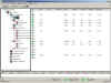
Where this is not enough, it is also possible to cascade multiple chassis in order to provide further expansion capabilities. With cascading, conferencing capacity is unlimited, yet all chassis� can still be controlled from a single management interface if required. This allows the MGC to provide an extremely high-capacity multipoint conferencing capability for both centralised and decentralised conferencing environments. The MGC-100 supports a family of management applications designed to allow users to manage the system and conferences in the most convenient manner. The MGC-100 can be managed via a Windows/NT application (communicating over the Internet, intranet or dial-up modem), Internet web browser or touch-tone telephone. MGC Manager is a comprehensive application for managing the MGC-100 system and conferences running on it. MGC Manager is a Windows/NT application that communicates with the MGC-100 via Internet, intranet or dial-up modem connections.
A familiar Explorer-like hierarchical tree menu in the left-hand pane provides easy access to various system management and conference control functions. Clicking on any of the menu entries brings up a more detailed view in the right hand pane. From here, the administrator can monitor systems status, view and change system configurations or perform troubleshooting diagnostics on any of the MCUs that are accessible over the network. It is also possible to schedule conferences for a set time in the future (and with set participants), initiate ad-hoc conferences, and manage ongoing conferences (remove or introduce users, change the continuous presence display, and so on). MGC Manager can operate effectively in both centralised and distributed environments. Each MGC system can support up to 16 simultaneous MGC Manager sessions, and a single MGC Manager session can also manage an unlimited number of MGC systems simultaneously. WebCommander is an Internet-based application for monitoring, managing and scheduling videoconferences from an Internet web browser. WebCommander resides on a web server that communicates with the MGC-100 via an IP connection and enables users to take complete control of their own conferences. Through WebCommander, users can schedule conferences and decide who will attend, as well as monitor and manage ongoing conferences. Users have access to an extensive number of management functions including the ability to change video display layouts, mute and unmute audio or video of individual sites, connect or disconnect sites, and terminate the conference. Touch Tone Conference Manager is an Interactive Voice Response (IVR) application to enable users to manage their own videoconferences using a touch tone telephone. TTCM uses interactive voice prompts to guide users through a selection of customisable management options (similar to those available in WebCommander) which they select using their touch tone telephone keypad. The MGC-100 has a full-blown H.323 proxy firewall built in, thus allowing it to be deployed at the edge of an IP network in parallel with an existing firewall. Unlike a general purpose firewall, the MGC-100 has one task � to manage H.323 sessions in a secure manner � and thus provides much higher levels of both performance and security. As part of the extensive testing we performed on this product, we installed the MGC-100 in the standard NSS firewall test rig, where it formed the only connection between the protected network and the outside world. The unit was then subjected to the normal battery of tests employed during NSS firewall certification procedures (see Appendix A) in an attempt to force traffic through the device. All tests were repeated both with and without active conference sessions operating through the MGC-100. At no time were our technicians able to force invalid data through the device, or hijack existing H.323 sessions in order to corrupt or �piggyback� data travelling through to the protected network. We also ran a battery of Denial of Service attacks on the MGC-100, which did have some success. It is possible to effect a DOS attack against a single Ethernet interface at a time (either internal or external), but the interface fails in a closed condition, thus prohibiting transfer of any traffic (even a legitimate H.323 session) until the interface is power cycled. Note that the only conference session affected is the one associated with the interface which has been attacked � all other conference sessions remain active. To date, the biggest market for H.323 applications has been Voice over IP (VoIP), but that may be set to change � albeit slowly. Until now, low bit rate Internet connections have made video- and data-intensive applications less appealing, whilst many companies can provide VoIP services today at a relatively low cost. With newer technologies such as Gigabit Ethernet and DSL, broadband connectivity is becoming more widespread and more accessible to smaller organisations. As bandwidth costs are driven down, data and videoconferencing applications are likely to become more pervasive. As organisations migrate from the PSTN to the IP world for their rich media communication needs, they require devices that will provide seamless transition, as well as allow compatibility with the widest possible range of devices. The MGC-100 (and MGC-50) provides this, with broad standards support, excellent scalability, and advanced Transcoding. This allows almost any device to communicate with almost any other in a seamless manner, and provides excellent interworking between IP networks and the PSTN. But all this would be moot if the introduction of such a device at the network edge provided yet another route for the hacker into the corporate network. Polycom Network Systems has worked hard on the firewall capabilities of the MGC range, and these devices passed all of our penetration tests and seem well able to stand up to any attack that is likely to be made against it when deployed in parallel with a traditional firewall. Both the MGC-100 and MGC-50 are awarded NSS Approved status.
Contact:
Polycom, Inc. Network
Systems Group Testing procedures for the Polycom Network System�s MGC-100 have been modified from the standard NSS Group firewall certification testing procedure since the MGC-100 has significant differences from a standard firewall: There is no concept of internal, external or DMZ interfaces. Thus it is not necessary to run multiple sequences of tests against different interfaces since they are all treated equally by the MGC-100 There is no �security policy� � the sole task of the MGC-100 is to manage H.323 sessions securely The MGC-100 is not expected to perform the same level of logging as a traditional firewall device It is necessary to run multiple sequences of tests � one with a videoconference session active and one with no session active � to ensure that there is no difference in security stance when active sessions are running Valid videoconference sessions are used to determine whether DOS attacks have been effective NSS Network Testing Laboratories maintains a dedicated test network for firewall accreditation (a network diagram is available on request). The test environment consists of two distinct networks � the external (Internet), and internal (protected) The internal network consists of a Telnet host, DNS server, SMTP server, file/print server, and Web server Machines on the internal network are not configured in a secure manner � they rely totally on the protection of the MGC-100 The MGC-100 is the only link between the internal and external networks The link between the MGC-100 and the external network is via a simple router. No packet filtering will be configured on this router � all protection must be provided by the MGC-100 A network monitor, protocol analyser and security monitor is installed on the external and internal networks Services The MGC-100 is to be configured to allow videoconference sessions between two IP devices (Tandberg videoconference endpoints) only Tests A range of tests will be carried out using commonly-available firewall scanning tools (NAI CyberCop Scanner and ISS Internet Scanner) as well as custom-built utilities. All tools will be configured with full knowledge of both the MGC-100 and network configuration: Check that firewall management console is not available to any users unless authenticated Check that the remote management link (if available) is encrypted or can be disabled Check that the firewall configuration is fully protected and tamper proof Check that the firewall is resistant to a range of known Denial Of Service (DOS) tests Check that the firewall has no known vulnerabilities. Check that the underlying OS is hardened and not vulnerable to known OS-specific attacks Check that only H.323 services (and no others) are available through the MGC-100 Check that the firewall does not allow uncontrolled access to the internal network Check that the firewall does not pass mis-configured packets to the internal network Tests will be repeated in the following manner: Stage 1: Probe the MGC-100 from the Internet � no videoconference sessions active Stage 2: Probe the protected network (through the MGC-100) from the Internet � no videoconference sessions active Stage 3: Probe the MGC-100 from the Internet � with videoconference sessions active Stage 4: Probe the protected network (through the MGC-100) from the Internet � with videoconference sessions active Stage 5: Attack the MGC-100 with a range of common Denial of Service attacks � no videoconference sessions active Stage 6: Attack the MGC-100 with a range of common Denial of Service attacks � with videoconference sessions active Results Protocol analysers, network monitors and advanced security monitoring tools are used during initial configuration and throughout the testing, both to validate the configuration and confirm the test results. A device which passes these tests should be capable of ensuring that: No access to protected servers is permitted No internal data is allowed outside the protected network No �illegal� traffic is permitted on any protected segment No access to the management console or firewall configuration files is allowed The device remains operative through DOS attacks (both generic IP and OS-specific attacks). Where it is recognised that a particular DoS attack has no defence, the device should terminate �gracefully� (leaving connections securely closed). The management console remains available and secure |
Security Testing |
Send mail to webmaster
with questions or
|